


Aerotech® AeroSpeed 2.4
More about Aerotech® AeroSpeed 2.4
Used to regulate the environment in livestock buildings, the Aerotech AeroSpeed 2.4 maintains your desired temperature in the facility by controlling the operation of ventilation and heating equipment. Two stages of variable speed cooling fans, two stages of constant-speed cooling fans, and two stages of either constant-speed cooling fans or heaters can be connected to the controller. In addition, the last cooling stage can be configured as a mist cooling stage.
Features of the ST 5222:
-
Three Digit Display
- Provides a high level of accuracy, allowing you to specify a temperature to within 1/10 of a degree (in Fahrenheit or Celsius units)
-
Pilot Lights
- Indicate the state of outputs allow you to monitor the operation of the system without having to enter the building
-
Minimum Ventilation Cycle
- When ventilation is not required for cooling, the first stage fans can be operated either continuously or intermittently to reduce the level of humidity and supply oxygen to the room
-
Temperature & Minimum Ventilation Speed Curves
- Can be set to automatically change the temperature set point and minimum ventilation speed over a given period of time in accordance with your requirements by specifying a temperature curve and a minimum ventilation speed curve with up to 6 different points each
-
Choice of 5 Motor Curves
- The variation in motor speed resulting in a change in voltage will depend on the make and capacity of the motor. In order to achieve a high degree of compatibility between controller and motor, you can choose from among 5 different motor curves, to ensure the correct voltage is supplied
-
Full Speed Fan Start-Up
- To overcome the inertia of the ventilation system components and de-ice the fan blades in cold weather conditions, the controller supplies maximum voltage to the variable speed fans for 2 sec immediately following each start-up
-
4 Independent Temperature Probe Inputs
- Up to 4 temperature probes can be connected to obtain a more accurate reading of the average room temperature and a faster reaction time
-
Overload and Overvoltage Protection
- Fuses are installed at the input and outputs to protect its circuitry in the case of an overload or overvoltage
-
Computer Control
- Can be connected to a computer, making it possible to centralize the management of information and diversify control strategies
Several Models To Choose From. Features of All Models:
- Fully adjustable temperature and ventilation curves
- Variable speed outputs have optional timer option
- Minimum, maximum temperature recordings
- 12' sensor included
- 120/240 volt
- 10 amp maximum fan load
2.4 Technical Specifications:
-
Supply:
- 115/230 VAC (-18%-+8%), 60 Hz, L1 same phases as Stage 1, overload and overvoltage protection fuse F11-1A fast blow
- 12 VDC for AC back-up supply; can activate stages 3-6 if supplied with DC back-up voltage
-
Stage 1:
- Variable output, 60 Hz, 10A fan (3/4 HP/115 VAC)/(1.5 HP/230 VAC), fuse F1-15A slow blow
-
Stage 2:
- Variable output, 60 Hz, 10A fan (3/4 HP/115 VAC)/(1.5 HP/230 VAC), fuse F8-15A slow blow
-
Stage 3:
- On/Off output, 115/230 VAC, 60 Hz, 30 VDC, 6A Fan, 10A res, fuse F3-15A slow blow
-
Stage 4:
- On/Off output, 115/230 VAC, 60 Hz, 30 VDC, 6A Fan, 10A res, fuse F4-15A slow blow
-
Stage 5:
- On/Off output, 115/230 VAC, 60 Hz, 30 VDC, 6A Fan, 10A res, fuse F5-15A slow blow
-
Stage 6:
- On/Off output, 115/230 VAC, 60 Hz, 30 VDC, 6A Fan, 10A res, heating, fuse F6-15A slow blow
-
Alarm:
- On/Off output, 115/230 VAC, 60 Hz, 30 VDC, 3A, fuse F7-3A slow blow
-
Probes:
- Low voltage (<5V), isolated from the supply. Operating range: -40° F to 120° F. Accuracy: 1.8° F between 41° F and 95° F
-
Enclosure:
- ABS, moisture and dust-tight
- The room temperature where the controller is located MUST ALWAYS REMAIN between 32° F and 104° F
Factory Settings:
| Parameter | Factory Setting | Range of Values | |
|---|---|---|---|
| Temperature Set Point | 75° F | -40° F to 99.9° F | |
| Stage 1 | Minimum Speed | 40% | 10%-100% |
| Time On | 15 sec | 0-900 seconds by increments of 15 sec |
|
| Time Off | 0 sec | ||
| Bandwidth | 3° F | 0.5° F - 20° F | |
| Stage 2 | Minimum Speed | 40% | 10%-100% |
| Starting Temp | 78.5° F | Set point + bandwidth to set point + bandwidth +20° F |
|
| Bandwidth | 3° F | 0.5° - 20° F | |
| Stage 3 | Starting Temp | 83.5° F | Stage 2 starting temp + 0.5° F to Stage 3 starting temp + 20° F |
| Stage 4 | Starting Temp | 85.5° F | Stage 3 starting temp + 0.5° F to Stage 4 starting temp + 20° F |
| Stage 5 | Starting Temp | 87.5° F | Stage 4 starting temp + 0.5° F to Stage 4 + starting temp + 20° F |
| Stage 6 | Starting Temp | 89.5° F | Stage 5 starting temp + 0.5° F to Stage 5 starting temp + 20° F |
| Mist | Time On | 1 min | 0-60 min |
| Time Off | 0 min | ||
| Heater A Starting Temp | 72.5° F | Off temp -0.5° to off temp -20° F |
|
| Heater B Starting Temp | 70.5° F | Heater A starting temp -0.5° F to Heater A starting temp -20° F |
|
| Heater A/B Off Temp | 74.5° F | Set point -20° F to set point +10° F |
|
| Alarm | Low Temp | 65° F | 0.5° F - 40° F from set point |
| High Temp | 87° F | ||
These initial parameter settings will not be retained in the controller's memory. Each new setting will replace the preceding one.
If the power supply is cut off, the last parameter settings will be retained in the memory until the power is restored.
| Model | QC Part # | Mfg Part # | Variable Speed Outputs | Thermal Contacts | Cooling (only) Contact | Sensors (max) | PC Loop | Ramping Timer | Alarm Contacts |
|---|---|---|---|---|---|---|---|---|---|
| AeroSpeed 1.1 | 10860 | ST5110 | 1 | 1 | 9 | 4 | Yes | No | Yes |
| AeroSpeed 1.2 | 10861 | ST5120 | 1 | 2 | 1 | 4 | Yes | No | Yes |
| AeroSpeed 1.3 | 10862 | ST511 | 1 | 2 | 4 | 4 | Yes | No | Yes |
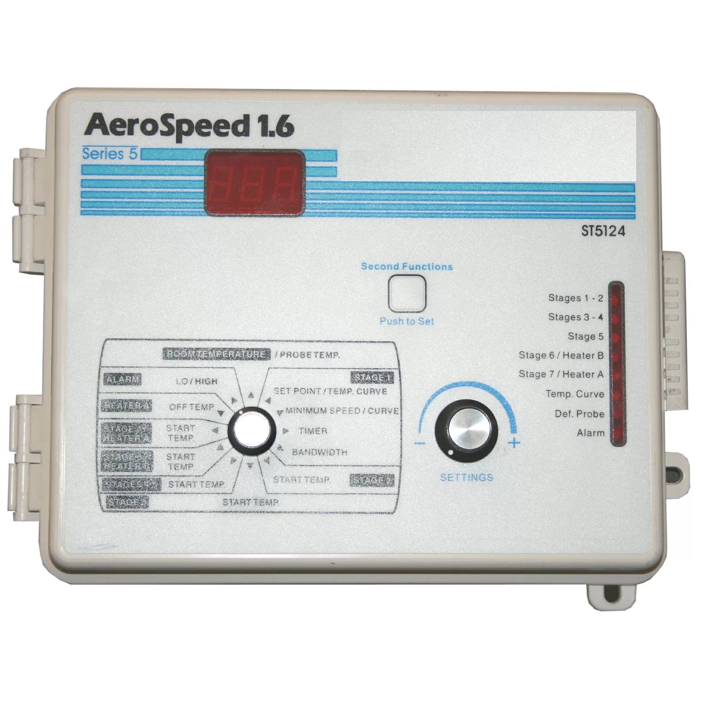
| AeroSpeed 1.6 | 10863 | ST5124 | 1 | 2 | - | 4 | Yes | No | Yes |
| AeroSpeed 2.2 | 10865 | ST5220 | 2 | 2 | 2 | 4 | Yes | No | Yes |
| AeroSpeed 2.4 | 10866 | ST5222 | 2 | 2 | 2 | 5 | Yes | Yes | Yes |